Pixy cmucam 5
September of last year I backed the Pixy CMUcam5 project on kickstarter. Back then the people behind the project (Charmed labs) promised a November delivery date. With over 2000 people backing the project things turned out a bit differently. I only received my Pixy last week. I also had the bad luck that the package was stuck at the Belgian customs, and I had to pay another 25€ import tax and VAT to receive my Pixy 🙁
The Pixy is a fast vision sensor that you can quickly “teach” to find objects. To do that the CMUcam 5 uses an Omnivision OV9715 image sensor and a NXP LPC4330, 204 MHz, dual core micro controller. The image sensor is fitted with a replaceable M12 lens. It comes with firmware and software to track objects based on color signatures. Pixy uses a hue-based color filtering algorithm to detect objects. Pixy remembers up to 7 different color signatures, so you can teach it to track 7 different objects with unique colors. It does this at a frame rate of 50 Hz. That’s pretty fast.
Pixy cmucam 5
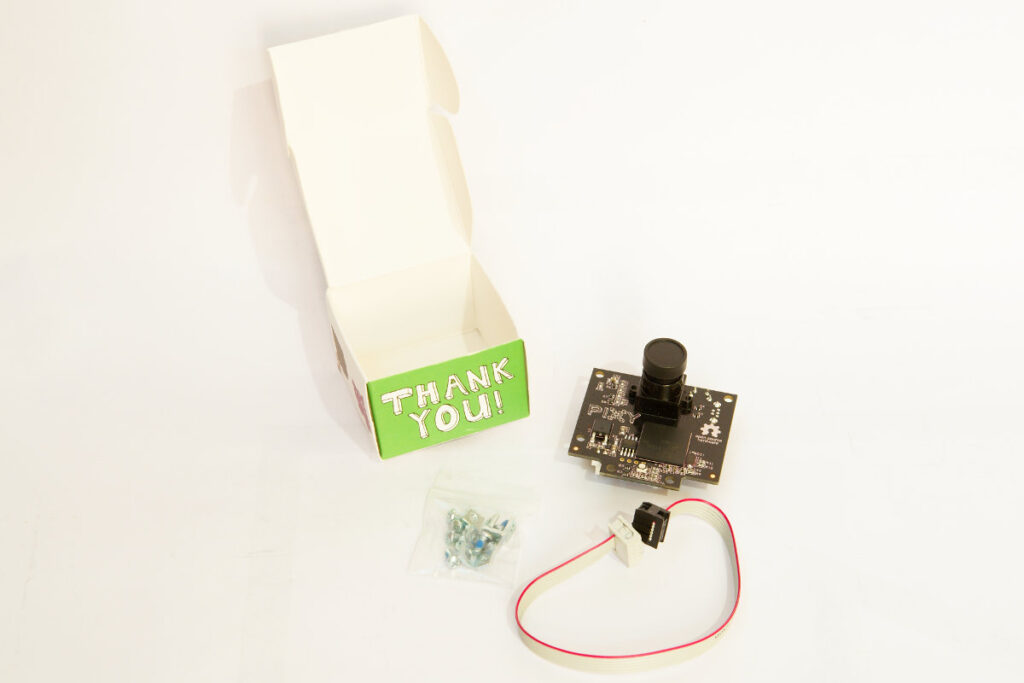
Pixy comes with a cable to connect it to the ICSP connector of an Arduino. In the box there was also a small bag with some screws and brackets. All the connectors are on the back of the board. There is a mini USB connector to hook it up to your PC. A 2 pin connector to power it, a 6 pin connector to hook up 2 servos. The most interesting connector for me is the 10 pin connector. This connector provides I2C, SPI and serial connections. So you can hook it up to whatever micro controller you want, the pins are 5V tolerant. I couldn’t find the pin out of the 10 pin connector on the Pixy wiki so I carefully did some testing to find out the pin out.
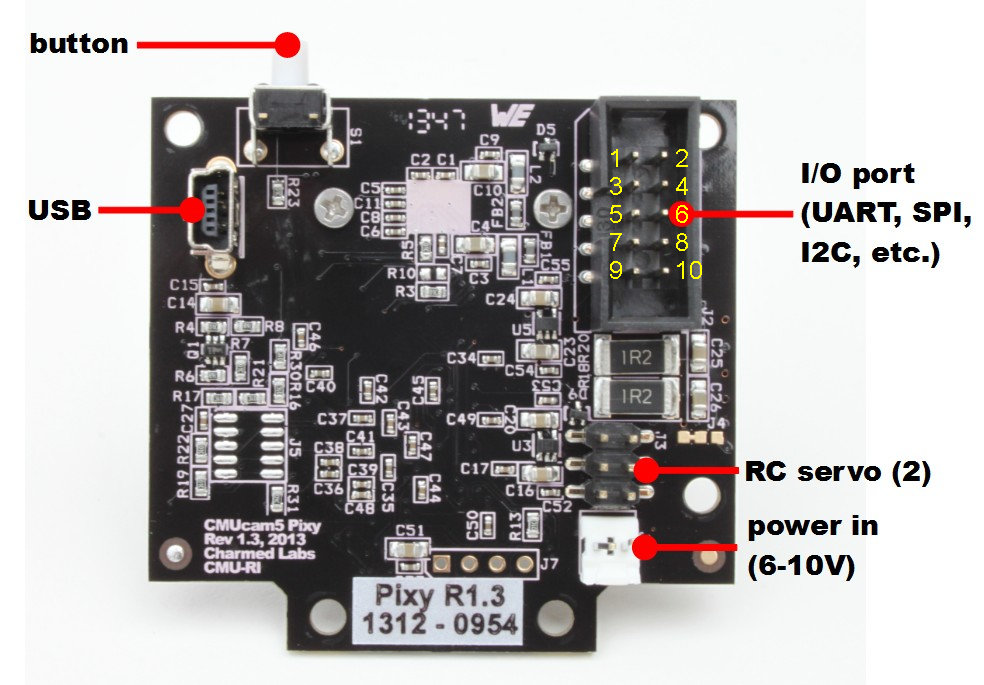
Pixy io connector pinout
Pin 1 = SPI MISO, UART RX, GPIO0 Pin 2 = 5V (in or out)
Pin 3 = SPI SCK, DAC out, GPIO1 Pin 4 = SPI MOSI, UART TX, GPIO2
Pin 5 = I2C SCL Pin 6 = GND
Pin 7 = SPI SS, ADC in, GPIO3 Pin 8 = GND
Pin 9 = I2C SDA Pin 10 = GND
Pixy comes with software to configure and set it up, Pixymon. You can download it from the CMUcam website. To install it on my Gentoo GNU/Linux workstation I had to modify the install script. I changed the “qmake-qt4” to qmake. The linux section in the buildpixymon.sh file should look like this:
if [[ “$platform” == ‘linux’ ]]; then
qmake pixymon.pro
make -w
cd ../../..
mkdir bin
cp src/host/pixymon/PixyMon bin
strip bin/PixyMon
cp src/host/pixymon/pixyflash.bin.hdr bin
fi
I installed the software as a regular user and fired it up without further problems. I then connected the Pixy to my PC with a mini USB cable.
There are 2 ways of teaching Pixy an object. You can just press the button on the Pixy and hold an object in front of it. Or you can teach it an object through the Pixymon software. In my experience it’s more accurate when using Pixymon. It’s also much handier when you want to teach it multiple objects. The software is very simple to use. In minutes I had the Pixy tracking on object. I was pretty amazed by the simplicity of the process.
Pixy has a connector to hook up 2 servos, as you can also buy a pan/tilt kit with it. I already have several cheap pan/tilt kits so I didn’t order one. The Pixymon software lets you set up the servos.
I wanted to learn how to process the data from the Pixy and decided not to use the servo outputs of the Pixy but let an Arduino control the servos. I used I2C to let the Pixy talk to an ATmega1284P. The Pixy outputs data in the form of one array per detected object. Each array contains the x and y position of the center of the object and the width and height of the object. This makes it very straightforward to process the data.
Some time ago I made a small robot with a WiiCamera sensor. The data it outputs is quite similar to the Pixy. So I dusted of my little robot and replaced the WiiCamera with the Pixy. I made some quick code changes, the result you can see in the following video:
The robot uses an ATmega1284 micro controller with an Arduino bootloader. The motors are controlled by an L293D H-bridge. The motors are fitted with encoders. This is the code I used for the video:
// http://wwww.bajdi.com
// Robot with 2 geared DC motors controlled by L293D, µCU = ATmega1284P-PU
// Pixy tracking object, communicates via I2C with µCU
// Pixy mounted on pan/tilt kit, 2 SG90 servos
// Robot will try to follow the object
// Pixy data:
// block 1 X = 0 object detected on the left
// block 1 X = 319 object detected on the right
// block 1 Y = 0 object detected top
// block 1 Y = 199 object detected bottom
// block 1 width = 1 to 320
// block 1 height = 1 to 200

#include <Servo.h>
#include <Wire.h>
#include <PixyI2C.h>

PixyI2C pixy;
uint16_t blocks;
unsigned int objectSize;
unsigned long pixyTime;

Servo panServo;
Servo tiltServo;
const int panServoLeft = 2100;
const int panServoCenter = 1450;
const int panServoRight = 750;
int panServoPos;
const int tiltServoUp = 2000;
const int tiltServoCenter = 1300;
const int tiltServoDown = 900;
int tiltServoPos;

const int EN1 = 3;        //pwm, enable motor 1 = pin 1 of L293D
const int direction1 = 13; //direcion motor 1 = pin 2 of L293D
const int EN2 = 14;        //pwm, enable motor 2 = pin 9 of L293D
const int direction2 = 15; //direction motor 2 = pin 15 of L293D

byte speedLeft = 100;
byte speedRight = 100;

const int lEncoder = 10;    // interrupt 0
const int rEncoder = 11;    // interrupt 1

const int motorTime = 100;
unsigned long encoderTime;
volatile unsigned long lpulse = 121;            // width of left and right encoder pulses in uS
volatile unsigned long rpulse = 121;            // width of left and right encoder pulses in uS
volatile unsigned long ltime;             // remembers time of left  encoders last state change in uS
volatile unsigned long rtime;             // remembers time of right encoders last state change in uS

void setup()
{
  Serial.begin(57600);
  pinMode(EN1, OUTPUT);
  pinMode(direction1, OUTPUT);
  pinMode(EN2, OUTPUT);
  pinMode(direction2, OUTPUT);
  analogWrite(EN1, 0);
  analogWrite(EN2, 0);
  digitalWrite(lEncoder,1);                               // enable pullup resistor for left  encoder sensor
  digitalWrite(rEncoder,1);
  attachInterrupt(0,Lencoder,CHANGE);                     // trigger left  encoder ISR on state change
  attachInterrupt(1,Rencoder,CHANGE);                     // trigger right encoder ISR on state change
  delay(50);
  panServo.attach(22);
  panServoPos = panServoCenter;
  panServo.writeMicroseconds(panServoPos);
  tiltServo.attach(23);
  tiltServoPos = tiltServoCenter;
  tiltServo.writeMicroseconds(tiltServoPos);
  delay(500);
}

void loop()
{

  if (millis() - encoderTime >= 5)
  {
    encoderTime = millis();
    int lastPulseL = millis() - ltime;     // Check how much time has passed since last pulse
    int lastPulseR = millis() - rtime;

    if (lastPulseL > motorTime && speedLeft < 170)    // If the pulse is longer then the time we want speed up motor
    {
      speedLeft = speedLeft+2;
    }
    if (lastPulseL < motorTime && speedLeft > 0)      // // If the pulse is shorter then the time we want slow down motor
    {
      speedLeft = speedLeft-2;
    }

    if (lastPulseR > motorTime && speedRight < 170)
    {
      speedRight = speedRight+2;
    }
    if (lastPulseR < motorTime && speedRight > 0)
    {
      speedRight = speedRight-2;
    }
  }


  if (millis() - pixyTime >= 20)
  {
    pixyTime = millis();
    blocks = pixy.getBlocks();

    if (blocks)        // object detected
    {

      objectSize = pixy.blocks[0].width * pixy.blocks[0].height;

      if(objectSize > 400)
      {
        if (pixy.blocks[0].x > 150 && panServoPos > panServoRight)
        {
          panServoPos -= 10;
        }
        if (pixy.blocks[0].x < 170 && panServoPos < panServoLeft)
        {
          panServoPos += 10;
        }
        if (pixy.blocks[0].y > 90 && tiltServoPos > tiltServoDown)
        {
          tiltServoPos -= 10;
        }
        if (pixy.blocks[0].y < 110 && tiltServoPos < tiltServoUp)
        {
          tiltServoPos += 10;
        }

        if (objectSize < 20000)  // object far from robot
        {
          if(panServoPos < panServoCenter+200 && panServoPos > panServoCenter-200)
          {
            forward();
          }
          if (panServoPos >= panServoCenter+200)
          {
            left();
          }
          if (panServoPos <= panServoCenter-200)
          {
            right();
          }
        }

        if (objectSize >= 20000)    // object close to robot
        {
          if(panServoPos < panServoCenter+200 && panServoPos > panServoCenter-200)
          {
            backward();
          }
          if (panServoPos >= panServoCenter+200)
          {
            left();
          }
          if (panServoPos <= panServoCenter-200)
          {
            right();
          }
        }
      }
      else
      {
        centerServo();
        stop();
      }
    }
    else
    {
      centerServo();
      stop();
    }

    panServo.writeMicroseconds(panServoPos);
    tiltServo.writeMicroseconds(tiltServoPos);
    Serial.print("pixy.blocks[0].x = ");
    Serial.println(pixy.blocks[0].x);
    Serial.print("pixy.blocks[0].y = ");
    Serial.println(pixy.blocks[0].y);
    Serial.print("pixy.blocks[0].width = ");
    Serial.println(pixy.blocks[0].width);
    Serial.print("pixy.blocks[0].height = ");
    Serial.println(pixy.blocks[0].height);
    Serial.print("objectSize = ");
    Serial.println(objectSize);
  }
}

void forward()
{
  digitalWrite(direction1, HIGH);
  digitalWrite(direction2, HIGH);
  analogWrite(EN1, speedLeft);
  analogWrite(EN2, speedRight);
}

void stop()
{
  digitalWrite(direction1, LOW);
  digitalWrite(direction2, LOW);
  analogWrite(EN1, 0);
  analogWrite(EN2, 0);
}

void backward()
{
  digitalWrite(direction1, LOW);
  digitalWrite(direction2, LOW);
  analogWrite(EN1, speedLeft);
  analogWrite(EN2, speedRight);
}

void left()
{
  digitalWrite(direction1, LOW);
  digitalWrite(direction2, HIGH);
  analogWrite(EN1, speedLeft);
  analogWrite(EN2, speedRight);
}

void right()
{
  digitalWrite(direction1, HIGH);
  digitalWrite(direction2, LOW);
  analogWrite(EN1, speedLeft);
  analogWrite(EN2, speedRight);
}

//======================================================= ISR for left encoder =======================================================
void Lencoder()
{
  lpulse=millis()-ltime;                               // time between last state change and this state change
  ltime=millis();  // update ltime with time of most recent state change
  //lcount++;
}


//======================================================= ISR for right encoder ======================================================
void Rencoder()
{
  rpulse=millis()-rtime;                               // time between last state change and this state change
  rtime=millis();  // update ltime with time of most recent state change
  //rcount++;
}

void centerServo()
{
  if (panServoPos > panServoCenter) // center pan servo
  {
    panServoPos -= 10;
  }
  if (panServoPos < panServoCenter)  // center pan servo
  {
    panServoPos += 10;
  }
  if (tiltServoPos > tiltServoCenter) // center tilt servo
  {
    tiltServoPos -= 10;
  }
  if (tiltServoPos < tiltServoCenter) // center tilt servo
  {
    tiltServoPos += 10;
  }
}
The Pixy is a fantastic and super easy to use vision sensor. If you’re a bit handy you can have a robot tracking an object in no time. At the moment the firmware only detects objects based on color. The makers of the Pixy are working on new firmware to track objects using color codes. That should make it possible to track more advanced objects. I did have some trouble with the camera, sometimes I could not get it to track an object. Luckily the Pixymon software lets you see what the camera is seeing. It was mainly caused by the bad lighting in my room, there was not enough color saturation in the object I wanted to track. You need a well lit space to make it a bit easier for the camera.