RP3d Prusa I3
I’ve been thinking about buying a 3D printer for more then a year. What put me of buying one is simple, time. I know people that have a reprap 3D printer, and from their experience I have learned that it’s a very time consuming device. And then I’m just talking about the printing part. Before you can start printing you need to 3D-design a part and then turn it into gcode. I’m not a mechanical designer and have little experience in 3D CAD design. That is a lot to learn = lots of time…
Then there is also the financial side. When 3D printers started to become popular, decent reprap kits in Europe cost +600€. That’s quite a bit of money for a hobby device that I might not use a lot. The last couple of years lots of Chinese manufacturers started selling parts for reprap 3D printers. In the beginning they only sold the electronics since they were all made over there. Then they started selling complete kits that included all the mechanical parts including the 3D printed parts. Not all is well though I’ve read numerous bad experiences, from controller boards with low quality parts on them to ramps boards with mosfets that were soldered the wrong way. I’ve read of people that bought a complete kit where the 3D printed parts fell apart when just unpacking them. I was very sceptical about buying such a kit from some unknown seller in China.
So about a couple of months ago someone gave me a link to an Aliexpress page where a Chinese company was offering a Prusa I3 kit for 199$. The catch of course was the shipping cost, 105$ by DHL. Still 304$ for a complete Prusa I3 kit looked like a good deal. Over the next 2 days I changed my mind a dozen times, but I finally clicked that “buy now” button and got the credit card out. I was going to built a Prusa I3 3D printer! Of course things didn’t really go to plan. The day I bought it was 3 days before Chinese new year. The seller sent me a friendly email that they would sent the printer ASAP after their Chinese new year holiday had ended. Which was about 2 weeks later. I could understand this situation. Most of China comes to a halt during the new years period. 2 weeks went by and I started checking my Aliexpress account, nothing seemed to be happening. After a couple of days I sent the seller a message. I got a prompt reply that my printer would be sent ASAP. And then the real adventure began, the next day I received a DHL tracking number.
It’s only then that I started realizing that I didn’t really knew what I had bought. So I started reading on the reprap website. I was getting really worried that this would turn in to a fiasco. Would I be able to print decent parts with my cheap China kit? I also searched the internet for people that had bought the same kit. My kit came from the Chinese company http://www.rp3d.com/. I found several forum posts of people that had bought the same kit. Some good experiences and some bad. I even found Youtube videos of someone assembling the same kit. I wasn’t alone 🙂
So the days went by and I kept checking the DHL tracking site to see where my printer was. I have very good experiences with having things delivered from China by DHL. Most stuff turns up in less then a week. This time was not different. While at work I suddenly got a telephone call from a Chinese number. The friendly people from rp3d where letting me know that my printer had arrived at my local DHL office and that I could pick it up. How is that for service 🙂 I picked up the big box from my local DHL office the next day. Took it home and unpacked it.
Unpacking my Pangu I3 kit:
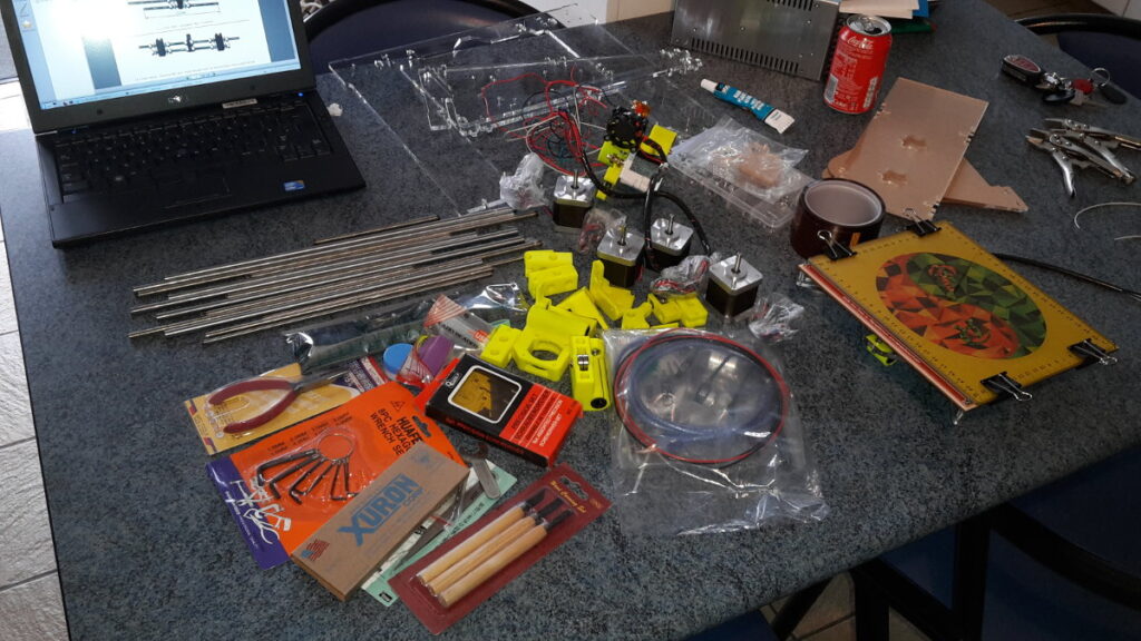
I was quite surprised when I unpacked all the parts. The kit didn’t only include the parts to built a 3D printer but also a lot of accessories that you need or are handy to built and use a 3D printer. I found an sd card between the numerous parts, it has the assembly instructions (pdf file) and a directory with photos that are a big help in building the kit. A kilo of PLA filament plus spool holder and a big roll of kapton tape was also included. Even all the tools needed to built the 3D printer were included. I got my moneys worth 🙂
2 days later on a Friday evening I started building the kit, and disaster struck. First thing I did was remove the wrap from the acrylic parts. The big chassis plate turned out to be cracked 🙁
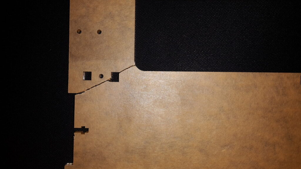
Cracked frame
The top right corner of the plate was completely cracked. I have to say that the kit was very well packaged. So I can’t really blame the seller. Thankfully I have glue that is suited for acrylic. I glued the plate and put some wrenches on it to hold it in place and went to bed.
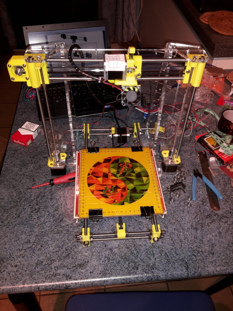
Next morning I checked the plate and tried to pull it apart, it was holding all right. My glue had done the trick. Now I could start building my 3D printer. The kit came with the heated bed and extruder already pre assembled.
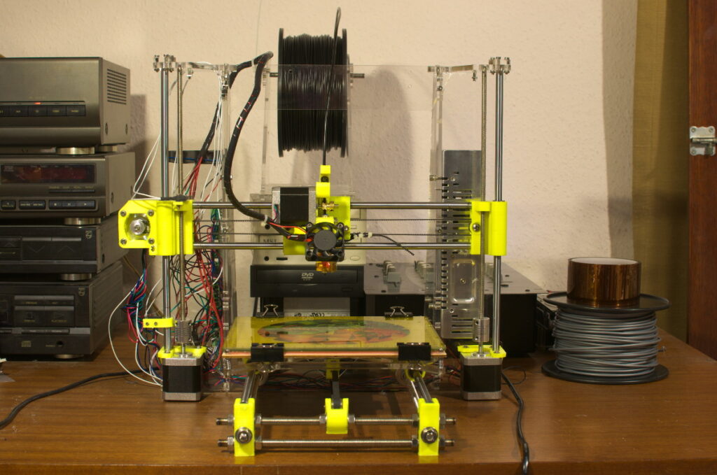
After about 5 hours of screwing all the parts together I had the following result:
Building it was not that hard. The 3d printed parts that came with the kit are of good quality. I just needed to drill holes in some of the parts to fit the M3 screws. The only issue I had was fixing the belts for the X and Y axis. The 3D printed parts that come with the kit could be improved in that respect. To fix the belt for the Y axis I used self tapping screws that I run through the belt in the 3D printed part that is fitted to the Y-carriage.
Then I needed to wire up the printer. The kit comes with a Melzi controller, unfortunately these boards don’t have the best reputation. Most of the wires are much to long so I created a big wire mess, but that’s something I didn’t worry about at that time.
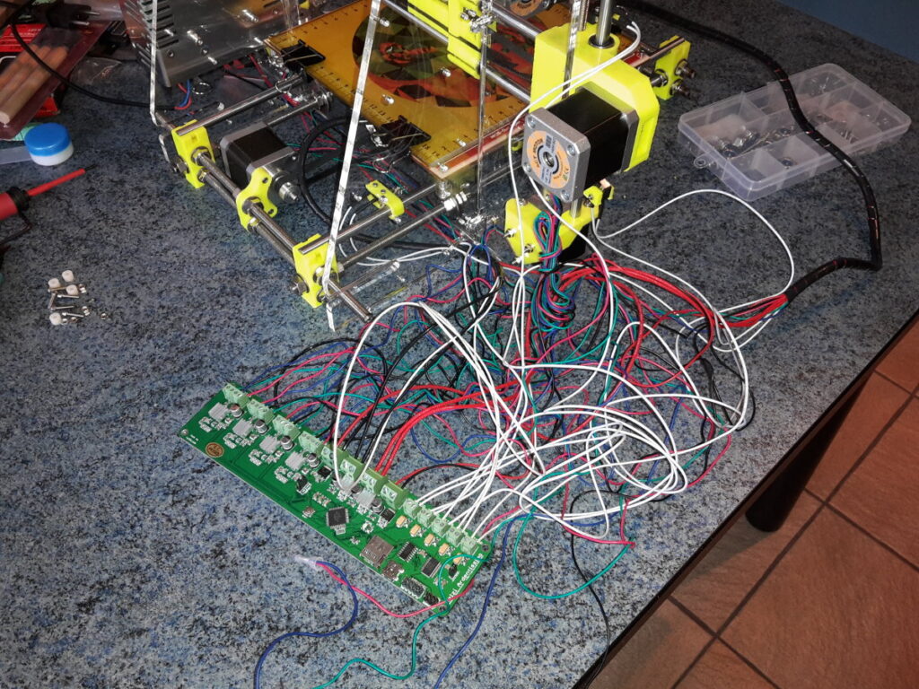
The Melzi controller came with firmware already loaded on to it. I installed the RepetierHost software on my laptop (which runs Gentoo GNU/Linux). RepetierHost lets you manually control the motors of your 3D printer. Success, I could move all the motors. I then tried heating the heated bed and extruder, all seemed to work as should. I then tried printing a 20mm cube and that didn’t turn out so well. It took me some time to find the right parameters to print decent parts. Most had to do with the temperature of the extruder. I now print PLA at +-185°C and set the hot bed at 55°C, this seems to work the best.
I did have some trouble with my X-axis. One of the LM8UU bearings in the X-carriage made a grinding noise, I immediately ordered some new ones and replaced the broken one. The hardest problem to fix was the backlash on the X-axis. It took me some time to find a reliable solution to fix and tighten the belt on the X-axis. This is the only complaint I have of the kit. On thingiverse there are a lot of improved parts for the Prusa I3 that take care of this problem.
In the following video you can see me trying to print a Euro coin holder.
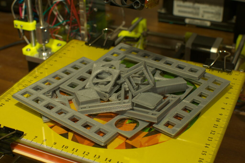
Because of the back lash on the X-belt I couldn’t print a nice round holder, the holder was more square then round. After I fixed the X-belt I could finally print nice round parts. I then started printing more calibration prints to see how accurate I could print. I used the following part on thingiverse to check the X and Y axis. To fine tune the X and Z axis I modified some settings in the Marlin configuration file. I also had to change the homing speed and acceleration settings else I would miss steps on the Z axis. All this fine tuning took me many hours of my free time. But now I have a reprap 3D printer that prints pretty accurate. I had to print quite a few parts to calibrate my printer:
My RP3D kit came with an extruder for 3mm filament and a nozzle of 0.4mm. It looks like the whole 3D printing world is shifting to 1.75mm filament. A nozzle of 0.4mm is not ideal to print really detailed fine parts. So that is something I might change in the near future. I’m very happy with my RP3D kit, I had not expected to be able to print nice parts in such a short time.