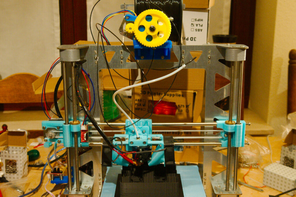
End of last year I decided to build a new 3D printer. At that time I already owned a very cheap Chinese Prusa I3 printer, it worked, but wasn’t a very reliable machine and it was dead slow. As I did not want to reuse any of the cheap Chinese parts of my old printer I decided to build a completely new machine using better parts. My goal was to build a reliable and fast machine.
I bought a P3steel chassis from a Spanish webshop, which turned out to be a very good base for a Prusa I3 style printer. It’s rock solid, easy and fast to bolt together and you need very few 3D printed parts. I bought Kysan 1124090 stepper motors for the X/Y axis, and 2 stepper motors with 8mm lead screws for the Z-axis. For the hot end I choose the popular E3D V6 for 1.75mm filament, with the bowden addon. Several people had recommended I go for a bowden setup if I wanted a fast machine. For the electronics I used the standard Arduino Mega + RAMPS setup with Marlin firmware. I put it together over several weeks as the various parts arrived. The last part to arrive was the extruder, which did cause me a bit of a headache…
What is printing fast? 100mm/sec sounds fast, but when your printing 0.1mm layers with a 0.25mm nozzle your only extruding 2.5mm³/sec. That is not hard on the extruder or hot end. Compare that to printing 0.25mm layers with a 0.4mm nozzle at 100mm/sec, then you are extruding 10mm³/sec of filament. It is a huge difference for the extruder and hot end. I bought a 0.35, 0.4 and a 0.6mm nozzle for my E3D hot end. Printing 0.4mm layers with a 0.6mm nozzle is very hard on the extruder.
You can slice a 10mm cube at 1000mm/sec in Cura or slic3r and successfully print it. Just set the acceleration in the firmware of your printer to a really low value (<1000) and it will print fine. But your printer will never get up to that speed. When printing a part like a 3DBenchy which requires a lot of small moves of the printer the key to a fast print is the acceleration settings in the firmware of your printer. I strongly recommend to try out and thoroughly test how high you can set the acceleration and jerk settings in your 3D printers firmware. This makes a huge difference in printing time. My machine can reliably move the X/Y axis at 250mm/sec with the acceleration set in Marlin at 8500. For print quality reasons I have lowered it to 6000.
So far I have only printed cheap Chinese PLA and Filaflex filaments, as I can’t stand the smell of ABS. But I would like to try PETG in the near future. I have 14 different colors of PLA in stock, I switch filaments a lot so an extruder that lets me switch filaments easily and quickly is a must for me.
I had not spent much time selecting an extruder. I had searched on Aliexpress and Ebay if there were any deals to be done and had found several cheap extruders from China. Worth a try I thought … I’m not so sure anymore, in the end I tried more then half a dozen extruders to find a solution that satisfied my requirements. I quickly realized that the extruder is one of the most important parts of the printer. Going cheap here is a bad idea.
I’m in no way a 3D printer guru. The following words are just my experiences of the various parts I tried out. I’m sure I made many mistakes along the way, but that is how we learn.
I spent hours printing test parts, trying out different printer parts and firmware/slicer settings. My favorite test print is the 3DBenchy. I mostly use Cura to slice, and have recently switched to version 2.1 beta.
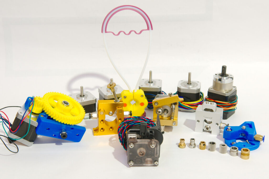
Here is my armada:

I have lost count how many 3DBenchy’s I have printed 😀
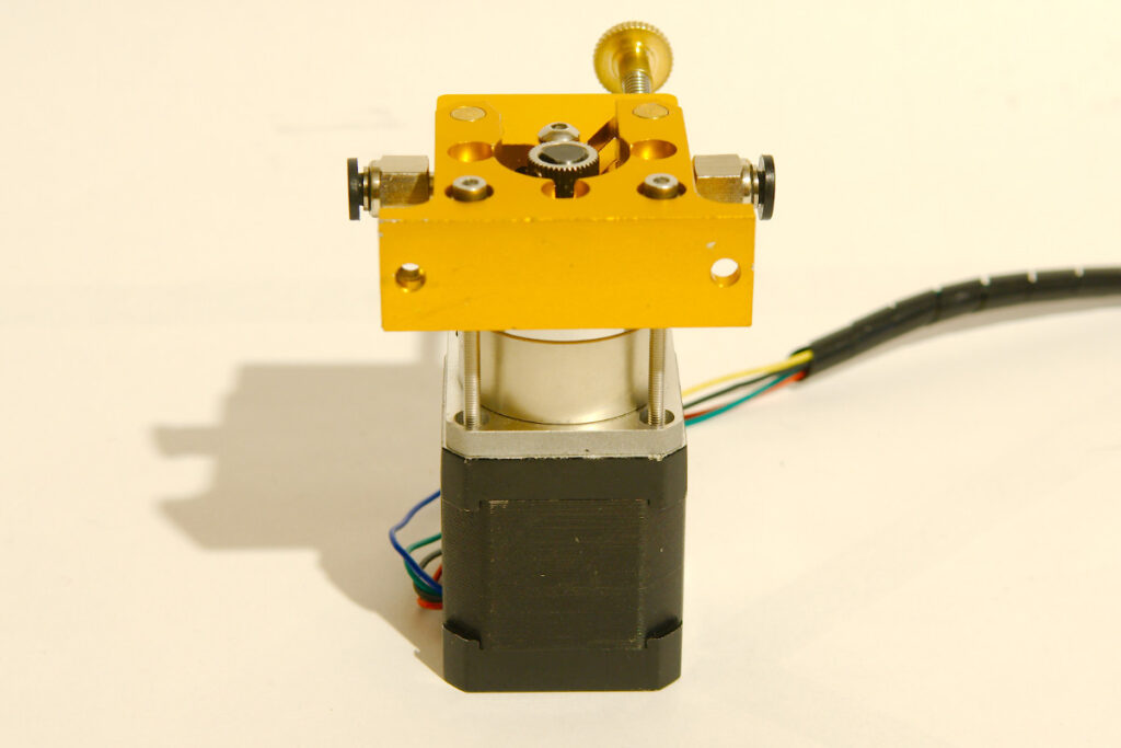
Simple direct drive extruder:
Direct drive extruder
I bought this cheap extruder including a small NEMA17 motor on Aliexpress. The motor that came with it was a pancake style motor rated at 0.4A with very low torque. I immediately knew that this was not going to work well. So I replaced the motor with a Kysan 1124090 stepper. I printed the first parts on my new printer with this extruder. It seemed to work well until I tried to print at faster speeds. The gap between the drive gear and the push fit coupling is to big. Every time I tried to raise the printing speed the filament collapsed inside the extruder and turned it into spaghetti. The drive gear that came with this extruder has very sharp teeth, when tightening the idler to much it will deform the filament or even worse it just shredded it to pieces. The fastest I could reliably print was at 60mm/sec printing 0.2mm layers with a 0.4mm nozzle. Not bad but I was looking for faster speeds.
Wades extruder
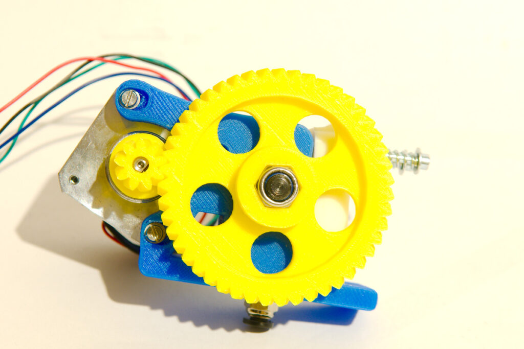
Wades extruder
Printed from stl files I found on Thingiverse, I used herringbone gears. All the parts were printed from PLA.
I ordered the following hobbed bolt on Ebay for my wades extruder:
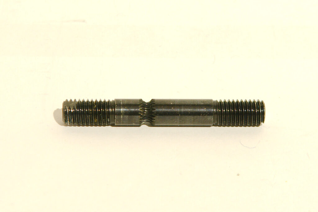
Hobbed bolt
After calibrating the extruder I switched to a 0.6mm nozzle to try and print big parts. I made some mistakes. I had not realized that printing thick 0.4mm layers with a 0.6mm nozzle would be so hard on the extruder. I had a slight mishap:
Extruder trouble
The wades extruder had pushed the bowden tube out of the push fit coupling, the push fit coupling turned out to be broken. This was caused by the following mistakes I made:
I had mounted the extruder on top of the chassis to keep the bowden tube as short as possible. This is not a good idea as the bend in the tube becomes very short as the hot end moves up creating a lot of resistance in the tube. I later moved the extruder to the side of the chassis with a longer bowden tube.
I was probably also printing at a to low temperature. The faster you push the filament through the hot end the less time it has to melt. So you need a higher temperature. I later found out that I need a temperature of +210°C when I print PLA at +10mm³/sec.
The wades extruder worked very good, after a bit of fine tuning I could reliably print at 85mm/sec 0.25mm layers with a 0.4mm nozzle (8.5mm³/sec). When trying to print faster the filament would start to slip no matter how hard I tightened the idler. Not bad but I wanted to go even faster.
I consider the wades extruder a good design, one of the reasons it’s so popular. It’s fairly easy to build, it uses simple parts. But it also has it’s downsides, the printed PLA gears will wear, best to print spares. Or even better print them from a tougher plastic. The PLA gears also made an annoying noise when retracting. Geared extruders don’t provide the fastest retraction and this can lead to stringing. I had to use longer retraction then with my previous extruder to get rid of stringing.
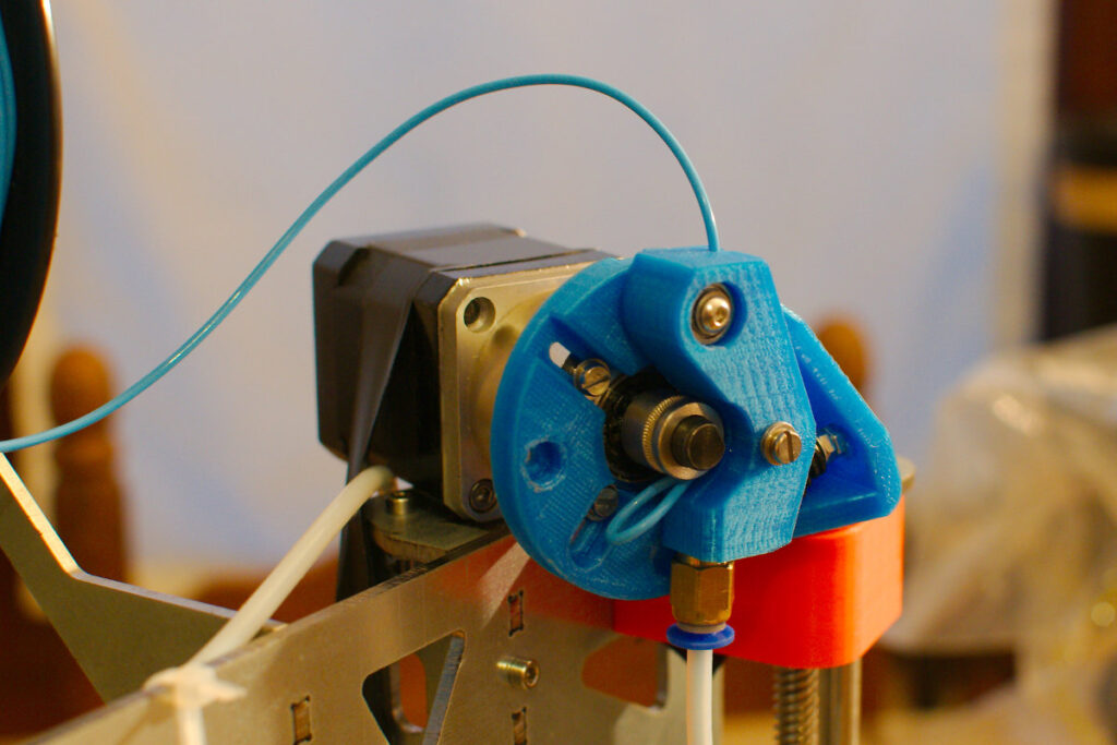
The B’struder
B struder
It was time to try out different solutions. I ordered a geared NEMA17 stepper motor (17HS15-1684S-PG5) on Aliexpress and started looking for designs that were suitable for this motor. I found the B’struder on Thingiverse, simple to print and it only uses a couple of small bearings which I happened to have in house. This design has a hole pattern to mount standard NEMA17 motors and geared NEMA17 stepper motors. It uses a spring to push the idler against the drive gear. The design doesn’t allow you to adjust the spring tension. I didn’t have a spring that was the right length so I modified the body of the extruder so I could use a shorter spring.
I needed a new drive gear that I could mount on the 8mm axle of the geared stepper motor. The one I bought didn’t turn out to be a good solution, it wasn’t suited for 1.75mm filament, another fail.
It’s the third one in this photo:
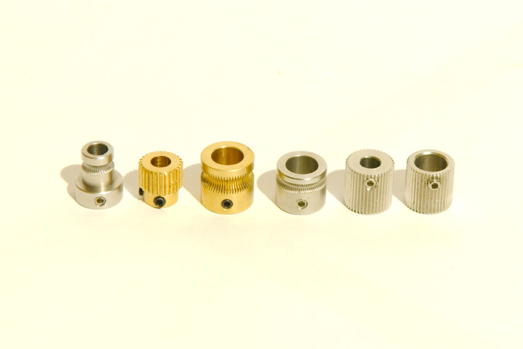
Hobbed pulleys
I never got good results with this extruder because of the big drive gear, it just hadn’t enough grip on the filament. I also came to the conclusion that the geared stepper motor is very slow to retract.
I later bought a new drive gear, the 4th one in the above photo. I tried to print Filaflex with it. But that was another failure. Filaflex is not the easiest filament to print…
Filaflex printing
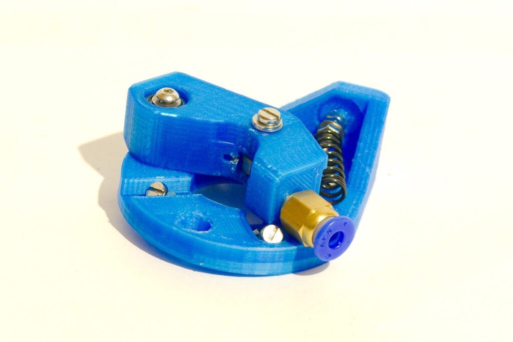
Saintflint extruder
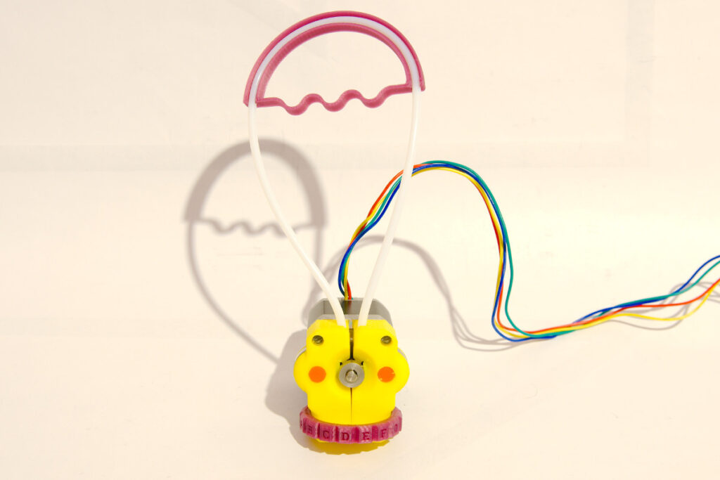
Saintflint extruder
I stumbled on this design while browsing the Google Plus 3D printing community. The files can be downloaded on Thingiverse. It’s a very different design then other extruders. I was quite skeptical of how it would turn out. But it actually works quite well. The only trouble I had with it was changing filament was a tedious task. The bowden tubes with the M4 nuts on the ends have to be perfectly aligned. I used a Kysan stepper motor and a small drive gear. I successfully printed several parts with it, only gave up on it after the bowden tube came loose out of one of the M4 nuts. (my fault hadn’t tightened it enough).
A video of the extruder in action:
Clone Bulldog light extruder
Bulldog extruder
Found this Chinese clone of the bulldog light extruder on Aliexpress. I uses 2 small springs to push the idler bearing against the drive gear, but you can’t adjust the spring tension. This doesn’t work very well, the bearing in the idler is flat so it doesn’t hold the filament in place. With the style of drive gear that comes with the extruder you really need a grooved bearing. The drive gear has quite a large diameter so you need a stepper motor with big torque. I used my strongest NEMA17 motor, a Kysan 1124090.
Bulldog extruder
To change filament I had to unbolt the front plate of the extruder and even then I had trouble to get the filament through the extruder. The gap between the body of the extruder and the drive gear is to big. The filament starts to bend and move around on the drive gear when trying to print at big speed. I quickly gave up on this one, not worth my time.
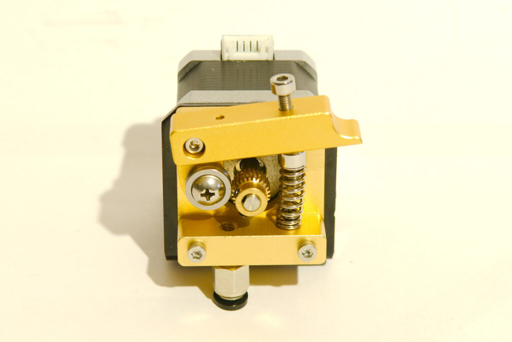
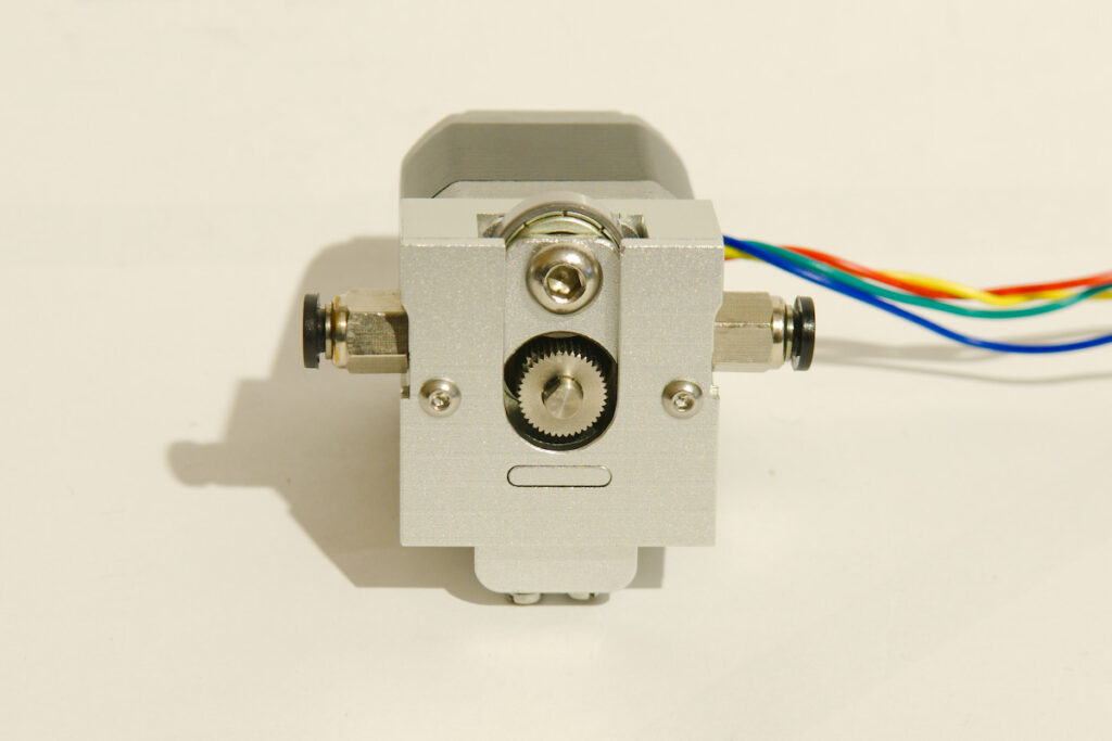
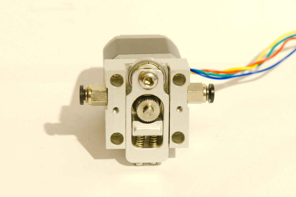
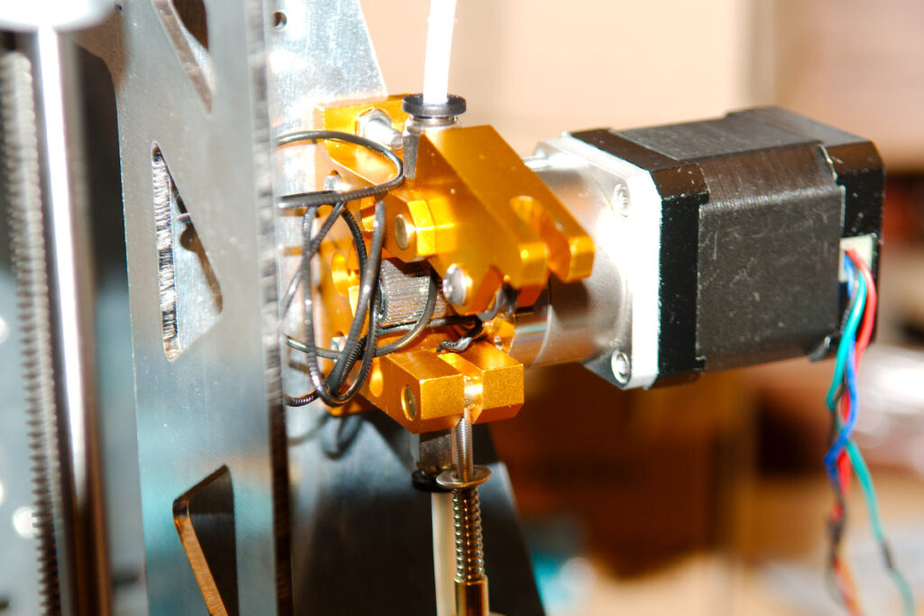
Another Chinese extruder
Geared extruder
Another Aliexpress catch, a simple aluminum extruder with a couple of good features. The idler tension can be easily adjusted and the idler has a grooved bearing to keep the filament in place. It came with a drive gear with an 8mm internal diameter. So I thought I would be able to just bolt my geared stepper motor to it. Another fail, it turned out to have a hole pattern for a standard NEMA17 motor. I luckily had some long M3 bolts and so I found a way to mount the geared stepper motor to it.
Geared extruder
The geared stepper motor has so much torque that it can push the push fit coupling to pieces if the hot end jams. I have only had jams with my E3D V6 hot end when printing at a to low temperature. I’ve destroyed a couple of push fit couplings that way. I bought 5 spares on Aliexpress to keep my printer going. I did have another issue with this extruder. When trying to extrude +10mm³/sec of filament the following would sometimes happen:
Geared extruder failure
Again caused by the big gap between the drive gear and the body of the extruder. This time I didn’t give up on the extruder and found a way to try and solve it. I put a small piece of PTFE tube between the drive gear and the push fit coupling. I have successfully printed some large parts printing 0.4mm layers with a 0.6mm nozzle @ 55mm/sec (13.2mm³/sec). Still this is not a perfect solution, when printing at these speeds the piece of bowden tube sometimes starts to bend. It has not led to any failed prints with normal PLA so far, but it does worry me. But even with this piece of bowden tube in place I cannot print Filaflex at very slow speeds.
The geared stepper motor has enormous torque but it doesn’t like fast acceleration/retraction, I had to print half a dozen test parts to find right retraction settings. But it will still cause a little bit of stringing when printing parts with lots of retraction. I have since used this extruder to print +5kg of PLA. I’ve printed big parts, and have done 6 hour prints with it without problems.
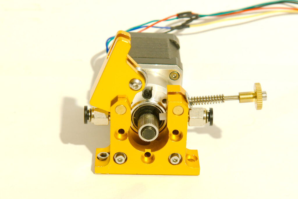
E3D Titan extruder

E3D titan extruder
Beginning of April E3D launched a new product, the Titan extruder. I had just failed to print Filaflex with a couple of the above extruders when I saw the announcement. Was I willing to spent more money on another extruder? And would the Titan be any good? I changed my mind a dozen times and early May I made up my mind and ordered one. The day after ordering it I got the confirmation that the package was on the way. To my surprise it took 20 days to arrive, I have received packages from China faster… Can’t blame E3D for this though, I had selected the cheapest shipping option, Royal Mail.
To save some money I bought the Titan extruder with the bowden addon but without the motor and mounting bracket. As the Titan is not exactly cheap, it cost me more then 70€. I have a large variety of spare stepper motors and one of the Chinese extruders came with a metal bracket that turned out to be a perfect fit to bolt the Titan to the side of my P3steel chassis.
Assembling the Titan is pretty easy although the instructions on the E3D wiki are not that easy to understand for a non native English speaker as me. E3D has provided the necessary information on their wiki to set up the firmware. I started my usual routine by printing a hollow cube with 2 shells so I could measure the walls and check if the extrusion was right. Turned out it was over extruding a bit, on closer inspection I noticed that the filament was sliding to the outer part of the drive gear which has a bigger diameter. The filament has to be fed perfectly straight in to the extruder to make sure it runs on the middle of the drive gear. Because of my setup where the spool sits on the top of the chassis and the extruder is on the side I use a PTFE tube to guide the filament. I had not inserted the PTFE tube fully in to the idler which made the filament run on the side of the drive gear. I had to use brute force to press the tube fully in to the idler.
I use an ACT NEMA17 stepper motor and I’m surprised with the swift retraction, I can easily retract at 70mm/sec with acceleration set to 8000 in Marlin. This is a lot faster then I could retract with my wades extruder and geared NEMA17 motor. And is about the same speed I used with the “ungeared” extruders that I’ve tested, more then fast enough to print without any stringing. I use 3mm of retraction with my E3D V6 hot end when printing PLA.
I’ve printed my first successful print in Filaflex filament with the Titan extruder. But I did take a couple attempts. But that has more to do with Filaflex, it’s so flexible which makes it very hard to print. It’s not really suited for printing with a bowden setup.
Conclusion
There are many extruders available, but a lot have the same fault. A giant gap between the drive gear and the output of the extruder. This makes it impossible to print flexible filament or to print at fast speeds.
I’m not going to recommend any extruder, it all depends on your printer and requirements. I’ve seen people that are successfully printing with their cheap Chinese or 3D printed extruder and that are happy with it.
The easiest solution is to buy an extruder like the E3D Titan. It works very well and you don’t have to spent any time calibrating it. But it comes at a price…